

Device And Principle Of STR Drive Axle
The STR drive axle consists of the main drive, differential, half-shaft, and axle housing. The function of the drive axle is to:
(1) transmit the engine torque from the gearbox and drive shaft to the drive wheels via the main drive, differential drive and half shafts, while ensuring a reduction in speed and an increase in torque.
(2) The change in direction of the torque transmitted by the main drive bevel gears.
(3 ) Enables the left and right wheels to rotate at different speeds (with the aid of a differential).
STR drive axle (see Figure 1.1)
The main drive train is one of the main components of the transmission and is used to reduce the speed and increase the torque. When there is no upshift in the transmission, the ratio of the main gear is at the same time the minimum ratio of the entire transmission. It is sometimes referred to as the “master ratio”. The differential is designed to solve the problem of different track lengths for the left and right drive wheels during cornering and to coordinate the work of multiple drive axles. The half-shafts are used to transmit torque to the wheels. The axle housing is the mounting base for the main transmission components.
All rear drive axles on heavy trucks are often referred to simply as “rear axles”. Most heavy trucks are equipped with two drive axles, but a few are equipped with only one drive axle. Trucks with two drive axles near the front of the vehicle are usually referred to as intermediate axles and the second drive axle as the rear axle. The drive axles of heavy trucks are divided into two options, STR and HW, depending on their constructional characteristics.
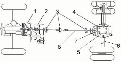
1 – clutch; 2 – gearbox; 3 – universal joint; 4 – drive axle; 5 – differential; 6 – half-shaft; 7-Main drive; 8-Driveshaft
The STR series drive axles are most commonly used on heavy-duty trucks. These bridges use STR’s technology and their presence for decades has proven their adaptability to Chinese operating conditions. They feature a single-stage main drive supplemented by wheel reduction gear.
Therefore, the STR series drive axles are actually equipped with a two-stage reduction gear, see Figure 1-2.
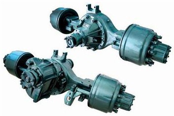
As with any drive axle, the STR series axle consists of the main drive, Differen-Ciala, half-shaft and axle housing.
1. Main drive
1.1.Central main drive
The overall situation of the STR series rear drive axle main drive is shown in Figure 1-3.
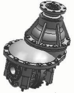
The main drive flange is connected to the drive shaft. The inner surface of the flange sleeve has a spline connected to the bevel gear 7 shaft spline so that the engine power is transmitted from the drive shaft universal joint to the gear 7, the main drive gear 7 rotates relative to its axis, where the gear shaft is held by two bevel bearings 4 and 6. Gear 7 engages with the driven bevel gear 9. The gear shaft and gear axis are perpendicular to each other. In the main drive, the rotation axis of the driven wheel on which the differential is fixed is rotated 90 degrees relative to the direction of the engine axis. In addition, the main drive gearing reduces the speed and increases the torque. The differential 15 mounted on the two bevel bearings 13 rotates with respect to the bearing axis and distributes the torque to the bevel gears of the two half shafts.

1 – flange retaining nut; 2 – flange; 3 – sealing sleeve assembly; 4, 6, 13 – tapered roller bearings; 5 – bearing housing shell; 7 – active bevel gear; 8 – main drive crankcase; 9 – driven bevel gear; 10 – adjusting nut; 11 – round nut; 12 – fixed gear; interlocking half-coupling; 14 – sealing ring; 15 – differential assembly
To ensure correct engagement, the load positions of the main drive’s main gear and driven wheel can be adjusted from the main drive. For this purpose, the adjustment washer not shown in Figures 1-4, which is located between the bearing housing 5 and the main transmission 8, should be used.
When the thickness of the adjusting washer is increased or decreased, the 5 cm bearing set moves up or down with the main bevel gear 7, thereby changing the relative position of the main gear to the driven wheel. On each side of the main drive are adjustment nuts 10 for the differential tapered roller bearings 13. When these nuts are unscrewed or tightened, the relative position of the driven gear 9 attached to the differential housing 15 is changed. The two controls described above allow the teeth of the active and driven bevel gears to engage correctly.
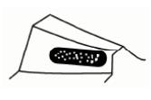
Before adjustment, a red pigment (a mixture of red tannin and oil) is applied to the teeth of the driven wheel, and then the main gear is manually turned forward and backward. Afterward, red marks will appear on the two working surfaces of the driven wheel teeth. The engagement is considered correct if the markings on both working surfaces of the driven wheel teeth are at a height in the middle of the tooth, slightly to the narrower part of the tooth, and occupy at least 60% of the tooth width. The contact points in correct engagement are shown in Figure 1-5.
The main drive gearbox is adjacent to the bridge gearbox. The bridge housing, the main drive housing 8, the bearing housing 5, the seal sleeve 3 assembly, the flange 2, the flange nut 1, and other components are therefore arranged in a confined space. In this enclosed space, there is a large amount of lubricant to reduce friction in rotation, for example in bearings and gears. Oil-proof silicone seals prevent oil from flowing through the contact surface joints between the main transmission and the axle housing, between the main transmission and the bearing housing, between the sealing sleeve assembly and the bearing housing, and between the flange nut and the flange. A sealing sleeve is provided between the bearing housing and the flange. The sealing sleeve does not prevent the flange from rotating relative to its axis but prevents the ingress of dust and the penetration of oil into the gap between the flange and the sealing sleeve.
2. Double axle main drive
The twin axle main drive is on the intermediate drive axle. It divides the power transmitted from the gearbox into two streams. One part of the power is transferred to the middle axle and the other part to the rear axle.
The STR series twin axle main drive diagram is shown in Figure 1-6.
1-6. The torque is transmitted via the driveshaft to the flange 4 and then to the axle (front) differential shaft via a splined connection. The central differential distributes torque MO-ME over the two half-shafts 13 and 16. torque is transmitted from the output half-shaft of the intermediate axle 32 to the output flange 29 and from the flange 29 to the rear axle via a single driveshaft. A cylindrical gear 19 is set in the splines of the hollow shaft 20. rotation is transmitted to the main drive bevel gears of the intermediate axle 35 via the cylindrical gear pairs 19 and 38. Further, after reducing the speed and increasing the torque in the main drive, the power is transmitted to the inter-wheel differential of the intermediate axle 34 via the bevel subsets 35 and 33. In addition, the system works in a similar way to the main drive and differential of a single rear axle.

1 – front (central) differential shaft; 2, 31 – flange retaining nut; 3, 30 – cotter pin; 4, 29 – -flange; 5, 27, 41 – bearing assembly; 6, 18, 21, 28 – ball bearing; 7 – locking ring; 8 – retaining pin; 9 -plug; 10 – pin; 11 – interlock switch sensor; 12 – front half-shaft gear washer; 13 – – front half-shaft gear; 14 – satellite dressing; 15 – central differential satellite; 16 – rear half-shaft gear; 17 – rear of differential housing; 19 – active cylindrical gear 20 – hollow shaft; 22 – spring ring; 23 – round nut; 24 – axle housing; 25 – half-shaft; 26 – sliding gear half coupling; 32 – intermediate axle output half-shaft; 33 – driven bevel gear; 34 – inter-wheel differential; 35 – active bevel gear; 36 – main bevel gear-active bevel gears; 36 – main transmission; 37 – cylindrical roller bearings; 38 – driven cylindrical gears; 39 – crankcase; 40 – separator sleeve; 42 – tapered roller bearings –tapered roller bearing; 43 – bearing outer ring pressure plate; 44 – crankcase cover; 45 – rear half-shaft gear washer; 46 – four-way.
We are a professional supplier of heavy truck and construction machinery parts for Sinotruk, High-Quality Heavy Truck Chassis Spare Parts, Economical Price, Fast Delivery, and Reliable Service Of Our Sitrak Spare Parts.


